Corporate Office Network
This post covers the device configurations. Topics like network security and design rationale are broken out into smaller separate posts for readability.
Contents
Network addressing
Private address ranges 172.16.0.0/16 and 10.0.0.0/8 were chosen to avoid subnet overlap when setting up remote access for employees in the future.
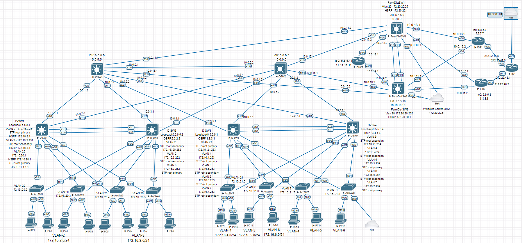
The network follows Cisco’s Enterprise Campus Architecture — a three-tier hierarchical model. The traffic split is approximately 80% internal and 20% external. Here’s what each tier handles:
Access Layer — each device handles no more than ~5% of total enterprise traffic on average.
Distribution Layer — each device handles no more than ~20% of total enterprise traffic on average.
Core Layer — each device handles no more than ~80% of total enterprise traffic on average (up to 100% is acceptable).
Traffic is divided into 9 VLANs:
2    ENGINEER
3    ACCOUNTING
4    LAWYER
5    SKLAD
6    PROVISION
7    IT
20   MANAGEMENT
21   MANAGEMENT
VLAN 20 MANAGEMENT was also added when deploying Windows Server in the 3rd Distribution block. The entire enterprise network is divided into 3 Distribution blocks connected hierarchically:
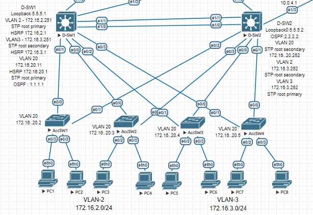
Block 1: D-SW1 and D-SW2
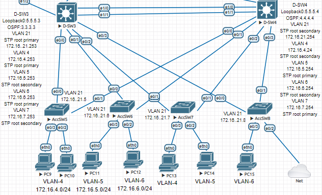
Block 2: D-SW3 and D-SW4
Block 3: FarmDistSW1 and FarmDistSW2
Everything below these devices is L2; everything above is L3.
STP, HSRP
HSRP is used for first-hop redundancy at the L2/L3 boundary for the first two blocks. The first challenge was STP (PVST), which builds a spanning tree per VLAN. The problem: STP blocks ports, causing traffic to route through access switches and breaking the hierarchical model.
Block 1 (D-SW1 and D-SW2) has 3 traffic domains: VLAN 2, 3, 20 — so 3 STP trees must align with the hierarchy. Root Primary and Root Secondary must be set manually.
Block 2 has 5 STP trees to configure.
Example configuration using D-SW1:
D-SW1 — STP priorities + HSRP + Loopback
enable
configure terminal
spanning-tree vlan 2,20 priority 24576
spanning-tree vlan 3 priority 28672
interface Vlan2
ip address 172.16.2.251 255.255.255.0
ip helper-address 5.5.5.11
standby 0 ip 172.16.2.1
standby 0 priority 150
standby 0 preempt
interface Vlan3
ip address 172.16.3.251 255.255.255.0
ip helper-address 5.5.5.11
standby 0 ip 172.16.3.1
standby 0 preempt
interface Loopback0
ip address 5.5.5.1 255.255.255.255
end
copy running-config startup-config
Same configuration applies to the other L3 Distribution switches.
OSPF and connectivity verification
IP addresses were assigned on all Router and L3 Switch interfaces, and OSPF was configured for dynamic routing.
D-SW1 — OSPF config
enable
configure terminal
router ospf 1
 router-id 1.1.1.1
 network 5.5.5.1 0.0.0.0 area 0
 network 10.0.1.0 0.0.0.3 area 0
 network 10.0.2.0 0.0.0.3 area 0
 network 172.16.2.0 0.0.0.255 area 0
 network 172.16.3.0 0.0.0.255 area 0
 network 172.16.20.0 0.0.0.255 area 0
interface Ethernet1/2
no switchport
ip address 10.0.1.1 255.255.255.252
ip ospf dead-interval 20
duplex auto
interface Ethernet1/3
no switchport
ip address 10.0.2.1 255.255.255.252
ip ospf dead-interval 20
duplex auto
end
copy running-config startup-config
Failover and convergence were tested at this stage.
DHCP and L2 Security
DHCP
DHCP server — excluded addresses + pools (all VLANs)
enable
configure terminal
ip dhcp excluded-address 172.16.2.1
ip dhcp excluded-address 172.16.3.1
ip dhcp excluded-address 172.16.4.1
ip dhcp excluded-address 172.16.5.1
ip dhcp excluded-address 172.16.6.1
ip dhcp excluded-address 172.16.7.1
ip dhcp excluded-address 172.16.20.1 172.16.20.5
ip dhcp excluded-address 172.16.21.1
ip dhcp excluded-address 172.16.21.5 172.16.21.8
ip dhcp excluded-address 172.16.2.251 172.16.2.252
ip dhcp excluded-address 172.16.3.251 172.16.3.252
ip dhcp excluded-address 172.16.3.253 172.16.3.254
ip dhcp excluded-address 172.16.4.253 172.16.4.254
ip dhcp excluded-address 172.16.5.253 172.16.5.254
ip dhcp excluded-address 172.16.6.253 172.16.6.254
ip dhcp excluded-address 172.16.7.253 172.16.7.254
ip dhcp pool VLAN2
network 172.16.2.0 255.255.255.0
default-router 172.16.2.1
dns-server 192.168.1.1
ip dhcp pool VLAN3
network 172.16.3.0 255.255.255.0
default-router 172.16.3.1
dns-server 192.168.1.1
ip dhcp pool VLAN4
network 172.16.4.0 255.255.255.0
default-router 172.16.4.1
dns-server 192.168.1.1
ip dhcp pool VLAN5
network 172.16.5.0 255.255.255.0
default-router 172.16.5.1
dns-server 192.168.1.1
ip dhcp pool VLAN6
network 172.16.6.0 255.255.255.0
default-router 172.16.6.1
dns-server 192.168.1.1
ip dhcp pool VLAN7
network 172.16.7.0 255.255.255.0
default-router 172.16.7.1
dns-server 192.168.1.1
end
copy running-config startup-config
VPCS — DHCP lease verification
VPCS> ip dhcp
DORA IP 172.16.2.2/24 GW 172.16.2.1
VPCS> show ip
NAME        : VPCS[1]
IP/MASK     : 172.16.2.2/24
GATEWAY     : 172.16.2.1
DNS         : 192.168.1.1
DHCP SERVER : 10.0.19.1
DHCP LEASE  : 86394, 86400/43200/75600
MAC         : 00:50:79:66:68:1d
MTU         : 1500
Switching security features configured:
- Port-security
Storm Control- DHCP Snooping
IP Source Guard- Dynamic ARP Inspection
Some technologies had to be dropped due to firmware limitations.
Port-security
Port-security limits which MAC addresses can send frames through a port — primarily a defense against MAC flooding attacks. Sticky learning is not used here since each port is limited to 2 MAC addresses, making static mode sufficient.
AccSW1 — port-security on access ports
enable
configure terminal
interface Ethernet0/2
 switchport access vlan 2
 switchport mode access
 switchport port-security maximum 2
 switchport port-security
interface Ethernet0/3
switchport access vlan 2
switchport mode access
switchport port-security maximum 2
switchport port-security
end
copy running-config startup-config
Configure on access ports only at the access layer.
Storm Control
Protects against broadcast storms by rate-limiting traffic when it exceeds a threshold. Not supported on these firmware images.
DHCP Snooping
Protects against DHCP-based attacks by distinguishing trusted (server-facing) and untrusted (client-facing) ports.
AccSW1 — DHCP Snooping
enable
configure terminal
interface Ethernet0/0
 ip dhcp snooping trust
interface Ethernet0/1
ip dhcp snooping trust
ip dhcp snooping
ip dhcp snooping vlan 2
no ip dhcp snooping information option
ip dhcp relay information trust-all
interface Ethernet0/2
ip dhcp snooping limit rate 10
interface Ethernet0/3
ip dhcp snooping limit rate 10
end
copy running-config startup-config
no ip dhcp snooping information option removes option 82 that snooping appends — without it, DHCP Discover frames are dropped at the Distribution layer.
IP Source Guard
Filters IP traffic on L2 interfaces based on the DHCP snooping binding table — defends against IP spoofing.
AccSW1(config-if)# ip verify source port-security
Traffic stopped flowing after this command and troubleshooting was unsuccessful — skipped.
Dynamic ARP Inspection
Protects against ARP spoofing attacks.
AccSW1 — Dynamic ARP Inspection
enable
configure terminal
ip arp inspection vlan 2
interface Ethernet0/0
ip arp inspection trust
interface Ethernet0/1
ip arp inspection trust
interface Ethernet0/2
ip arp inspection limit rate 2
interface Ethernet0/3
ip arp inspection limit rate 2
end
copy running-config startup-config
FTP, AAA server (Tacacs+), 3rd Distribution block, ISP, PAT
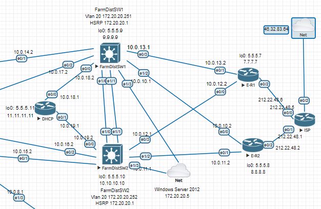
Internet access is provided through the 3rd Distribution block, which connects to Edge routers. The Edge routers implement PAT to translate private addresses into a single public IP. A dual-homed topology is used for provider redundancy.
PAT
E-R1 — PAT config
enable
configure terminal
interface Ethernet0/0
 ip address 10.0.12.2 255.255.255.252
 ip nat inside
interface Ethernet0/1
ip address 10.0.13.2 255.255.255.252
ip nat inside
interface Ethernet0/2
ip address 212.22.48.6 255.255.255.252
ip nat outside
ip nat inside source list 1 interface Ethernet0/2 overload
ip route 0.0.0.0 0.0.0.0 212.22.48.5
access-list 1 permit 172.16.0.0 0.0.15.255
access-list 1 permit 172.20.20.0 0.0.0.255
end
copy running-config startup-config
Windows Server 2012 with FTP Server is deployed in the 3rd block, connected with 2 bridged network adapters for HSRP-based failover.
interface Vlan20
 ip address 172.20.20.251 255.255.255.0
 standby 1 ip 172.20.20.1
 standby 1 priority 150
 standby 1 preempt

interface Ethernet1/3
 switchport access vlan 20
 switchport mode access
LACP
EtherChannel is configured on each distribution block.
D-SW4 — LACP EtherChannel config + verification
enable
configure terminal
interface Port-channel1
 switchport trunk encapsulation dot1q
 switchport mode trunk
interface Ethernet1/0
switchport trunk encapsulation dot1q
switchport mode trunk
channel-group 1 mode active
interface Ethernet1/1
switchport trunk encapsulation dot1q
switchport mode trunk
channel-group 1 mode active
port-channel load-balance src-dst-mac
D-SW4#show etherchannel summary
Group  Port-channel  Protocol    Ports
——+————-+———–+———————————————–
1      Po1(SU)         LACP      Et1/0(P)    Et1/1(P)
end
copy running-config startup-config
FTP
Automatic config archiving to FTP server on all devices:
login: admin | password: cisco
archive
 path ftp://admin:cisco@172.20.20.5/FarmDistSW1.txt
 write-memory
 time-period 360
NTP
Edge routers as NTP servers:
ntp source Loopback0
ntp master 5
ntp peer 5.5.5.8
ntp server ntp3.stratum2.ru
ntp server 1.ru.pool.ntp.org prefer
NTP clients:
ntp update-calendar
ntp server 5.5.5.8
ntp server 5.5.5.7 prefer
Network Engineer Course | Lab 17