PAT, DHCP, NTP
Assignment
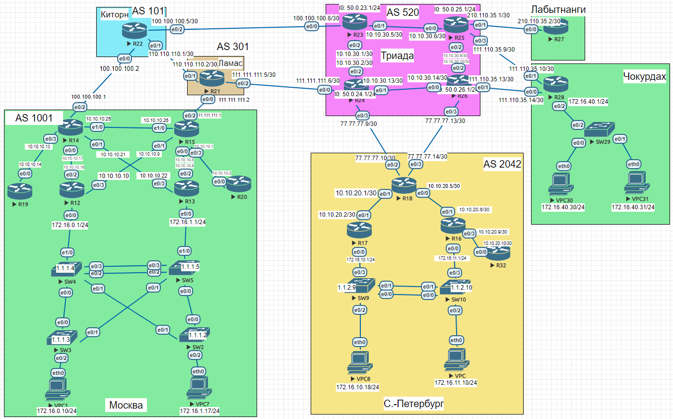
Goal: Configure DHCP in the Moscow office, configure time synchronization in the Moscow office, configure NAT in the Moscow, St. Petersburg, and Chokurdakh offices.
- Configure NAT(PAT) on R14 and R15 — translation must use the AS1001 address
- Configure NAT(PAT) on R18 — translation must use a pool of 5 addresses from AS2042
- Configure static NAT for R20
- Configure NAT so that R19 is reachable from any node for remote management
- Configure static NAT(PAT) for the Chokurdakh office
- Configure DHCP server in the Moscow office on R12 and R13 — VPC1 and VPC7 must receive network settings via DHCP
- Configure NTP server on R12 and R13 — all devices in the Moscow office must synchronize time with R12 and R13
- All offices in the lab must have IP connectivity
- Document the plan and changes
NAT(PAT) — Moscow R14 and R15
Translation uses the Loopback address from the AS1001 address space announced via BGP.
R14 — NAT config
enable
configure terminal
interface Ethernet0/0
 ip nat inside
interface Ethernet0/1
ip nat inside
interface Ethernet0/2
ip nat outside
interface Ethernet0/3
ip nat inside
interface Ethernet1/0
ip nat inside
ip nat pool OVRLD 200.20.20.14 200.20.20.14 netmask 255.255.252.0
ip nat inside source list 10 pool OVRLD overload
access-list 10 permit 10.10.10.0 0.0.0.31
end
copy running-config startup-config
R15 — NAT config
enable
configure terminal
interface Ethernet0/0
 ip nat inside
interface Ethernet0/1
ip nat inside
interface Ethernet0/2
ip nat outside
interface Ethernet0/3
ip nat inside
interface Ethernet1/0
ip nat inside
ip nat pool OVRLD 200.20.20.15 200.20.20.15 netmask 255.255.252.0
ip nat inside source list 10 pool OVRLD overload
access-list 10 permit 10.10.10.0 0.0.0.31
end
copy running-config startup-config
NAT(PAT) — St. Petersburg R18
R18 has two uplinks to Triada (R24 via e0/2, R26 via e0/3). Traffic is split between the two provider subnets: first half NATed behind 77.77.77.8/30, the other behind 77.77.77.12/30.
R18 — NAT config
enable
configure terminal
interface Ethernet0/0
 ip nat inside
interface Ethernet0/1
ip nat inside
interface Ethernet0/2
ip nat outside
interface Ethernet0/3
ip nat outside
ip nat pool OVRLD  77.77.77.10 77.77.77.10 netmask 255.255.255.252
ip nat pool OVRLD1 77.77.77.14 77.77.77.14 netmask 255.255.255.252
ip nat inside source list 10 pool OVRLD  overload
ip nat inside source list 11 pool OVRLD1 overload
access-list 10 permit 10.10.20.0 0.0.0.3
access-list 10 permit 172.16.10.0 0.0.0.255
access-list 11 permit 10.10.20.4 0.0.0.3
access-list 11 permit 10.10.20.8 0.0.0.3
access-list 11 permit 172.16.11.0 0.0.0.255
end
copy running-config startup-config
Static NAT for R20
R20’s internal Loopback address (1.1.1.19 space) is statically mapped to a public address in the 200.20.20.0/22 range. The same statement is applied on both R14 and R15 for redundancy.
R14 — static NAT for R20
enable
configure terminal
interface Loopback14
 ip address 200.20.20.14 255.255.252.0
ip nat inside source static 1.1.1.20 200.20.20.20
router bgp 1001
network 200.20.20.0 mask 255.255.252.0
end
copy running-config startup-config
R15 — static NAT for R20
enable
configure terminal
interface Loopback15
 ip address 200.20.20.15 255.255.252.0
ip nat inside source static 1.1.1.20 200.20.20.20
router bgp 1001
network 200.20.20.0 mask 255.255.252.0
end
copy running-config startup-config
Traffic is preferred through R15 — achieved at IGP (OSPF) and EGP (BGP) level. If R15 goes down, traffic automatically fails over to R14.
Traffic engineering — OSPF + BGP path selection
enable
configure terminal
! IGP: R15 advertises default with lower metric than R14
R14:
router ospf 1
 default-information originate metric 20
R15:
router ospf 1
default-information originate metric 10
! EGP: All routes from R21 pre-marked LP=150, beats R14.
! R14 prepends AS-path outbound to Kitorn to make its path less preferred.
R15:
router bgp 1001
neighbor 111.111.111.2 route-map LP in
route-map LP permit 10
set local-preference 150
R14:
route-map SET-ASPATH permit 10
set as-path prepend 1001 1001 1001
router bgp 1001
neighbor 100.100.100.2 route-map SET-ASPATH out
end
copy running-config startup-config
Verified with traceroute from Labytnangi and St. Petersburg:
R27 / R32 — traceroute to 200.20.20.20
R27>traceroute 200.20.20.20
  1 210.110.35.1 1 msec 0 msec 1 msec
  2 10.10.30.5 0 msec 0 msec 1 msec
  3 10.10.30.2 1 msec 1 msec 1 msec
  4 111.111.111.5 1 msec 1 msec 1 msec
  5 111.111.111.1 2 msec 2 msec 1 msec
  6 200.20.20.20 2 msec *  3 msec
R32>traceroute 200.20.20.20
1 10.10.20.9 0 msec 1 msec 0 msec
2 10.10.20.5 1 msec 0 msec 1 msec
3 77.77.77.13 [AS 520] 2 msec 1 msec 1 msec
4 10.10.30.13 2 msec 1 msec 2 msec
5 111.111.111.5 [AS 301] 1 msec 1 msec 1 msec
6 111.111.111.1 [AS 301] 2 msec 1 msec 1 msec
7 200.20.20.20 [AS 1001] 3 msec
NAT for R19 — remote management via SSH
Port-static NAT maps R19’s SSH port (TCP/22) to a public address in AS1001. Configured on both R14 and R15.
R14 / R15 — static PAT for SSH
enable
configure terminal
! R14:
interface Loopback14
 ip address 200.20.20.14 255.255.252.0
router bgp 1001
network 200.20.20.0 mask 255.255.252.0
ip nat inside source static tcp 1.1.1.19 22 200.20.20.19 22 extendable
! R15:
interface Loopback15
ip address 200.20.20.15 255.255.252.0
router bgp 1001
network 200.20.20.0 mask 255.255.252.0
ip nat inside source static tcp 1.1.1.19 22 200.20.20.19 22 extendable
end
copy running-config startup-config
R19 — SSH server setup
enable
configure terminal
hostname R19
ip domain-name Test
crypto key generate rsa
! [Enter] → 1024
line vty 0 4
transport input ssh
login local
username admin secret cisco
ip ssh version 2
enable secret cisco
interface Loopback19
ip address 1.1.1.19 255.255.255.255
router ospf 1
network 1.1.1.19 0.0.0.0 area 101
end
copy running-config startup-config
Static NAT — Chokurdakh (R28)
Chokurdakh needs at least a /29 prefix: –1 network, –1 loopback, –1 broadcast, –2 for static NAT entries = 5 addresses minimum.
R28 — NAT config
enable
configure terminal
interface Ethernet0/0
 ip nat outside
interface Ethernet0/1
ip nat outside
interface Ethernet0/2
ip nat inside
interface Loopback28
ip address 111.110.35.1 255.255.255.248
ip nat inside source static 172.16.40.30 111.110.35.5
ip nat inside source static 172.16.40.31 111.110.35.6
end
copy running-config startup-config
The /29 prefix must be announced via BGP and adjacent routers need a static route pointing to R28.
R25 / R26 — BGP announcement + static route + verification
enable
configure terminal
router bgp 520
 network 111.110.35.0 mask 255.255.255.248
! R26:
ip route 111.110.35.0 255.255.255.248 111.110.35.14
! R25:
ip route 111.110.35.0 255.255.255.248 111.110.35.10
! Verify:
R25#ping 111.110.35.5
!!!!!  Success rate is 100 percent (5/5), round-trip min/avg/max = 1/1/2 ms
R25#ping 111.110.35.6
!!!!!  Success rate is 100 percent (5/5), round-trip min/avg/max = 1/1/3 ms
DHCP — Moscow (R12 and R13)
R12 serves VPC1 (VLAN connected to R12), R13 serves VPC7.
R12:
ip dhcp excluded-address 172.16.0.1
ip dhcp pool DHCP12
 network 172.16.0.0 255.255.255.0
 default-router 172.16.0.1
R13:
ip dhcp excluded-address 172.16.1.1
ip dhcp pool DHCP13
 network 172.16.1.0 255.255.255.0
 default-router 172.16.1.1
Result:
VPC1:
VPCS> dhcp -r
DDORA IP 172.16.0.2/24 GW 172.16.0.1
VPC7:
VPCS> dhcp -r
DDORA IP 172.16.1.2/24 GW 172.16.1.1
NTP — Moscow office
R12 and R13 act as NTP masters (stratum 5). They broadcast NTP on VLAN 33 and uplink interfaces. R14, R15, R19, R20 sync via unicast to Loopback addresses. Switches sync via broadcast on the management VLAN.
R13 — NTP server
enable
configure terminal
interface Ethernet0/0.33
 encapsulation dot1Q 33
 ip address 1.2.1.253 255.255.255.0
 standby version 2
 standby 0 ip 1.2.1.1
 standby 0 preempt
 ntp broadcast
interface Ethernet0/2
ntp broadcast
interface Ethernet0/3
ntp broadcast
ntp source Loopback13
ntp master 5
ntp update-calendar
end
copy running-config startup-config
R12 — NTP server
enable
configure terminal
interface Ethernet0/0.33
 encapsulation dot1Q 33
 ip address 1.2.1.252 255.255.255.0
 standby version 2
 standby 0 ip 1.2.1.1
 standby 0 preempt
 ntp broadcast
interface Ethernet0/2
ntp broadcast
interface Ethernet0/3
ntp broadcast
ntp source Loopback12
ntp master 5
ntp update-calendar
end
copy running-config startup-config
R14 — NTP client + show ntp associations
enable
configure terminal
interface Ethernet0/0
ntp broadcast client
interface Ethernet0/1
ntp broadcast client
ntp server 1.1.1.12
ntp server 1.1.1.13
R14#show ntp associations
address ref clock st when poll reach delay offset disp
- 10.10.10.18 127.127.1.1 5 44 64 376 1.000 -0.500 2.890
+~1.1.1.12 127.127.1.1 5 151 256 377 0.000 0.000 2.541
+~1.1.1.13 127.127.1.1 5 34 64 377 0.000 0.000 4.007
- 10.10.10.22 127.127.1.1 5 34 64 376 0.000 0.000 2.902
end
copy running-config startup-config
R15 — NTP client + show ntp associations
enable
configure terminal
interface Ethernet0/0
ntp broadcast client
interface Ethernet0/1
ntp broadcast client
ntp server 1.1.1.12
ntp server 1.1.1.13
R15#show ntp associations
address ref clock st when poll reach delay offset disp
+~1.1.1.12 127.127.1.1 5 110 128 377 0.000 0.000 5.376
+~1.1.1.13 127.127.1.1 5 95 128 377 0.000 0.000 3.409
- 10.10.10.6 127.127.1.1 5 13 64 377 1.000 0.500 2.894
R20 — NTP client + show ntp associations
enable
configure terminal
interface Ethernet0/0
 ntp broadcast client
ntp server 1.1.1.12
ntp server 1.1.1.13
R20#show ntp associations
address         ref clock       st   when   poll reach  delay  offset   disp
*~1.1.1.12        127.127.1.1      5    612   1024   377  1.000  -0.500  2.038
+~1.1.1.13        127.127.1.1      5    158   1024   377  0.000   0.000  2.046
end
copy running-config startup-config
R19 — NTP client + show ntp associations
enable
configure terminal
interface Ethernet0/0
 ntp broadcast client
ntp server 1.1.1.12
ntp server 1.1.1.13
R19#show ntp associations
address         ref clock       st   when   poll reach  delay  offset   disp
*~1.1.1.12        127.127.1.1      5    810   1024   377  1.000  -0.500  2.008
+~1.1.1.13        127.127.1.1      5    613   1024   377  1.000  -0.500  1.974
end
copy running-config startup-config
Switches receive NTP via broadcast on VLAN 33 — no direct unicast config needed since R12/R13 are on the same broadcast domain via HSRP.
SW2 / SW3 / SW4 / SW5 — NTP (SW4 example)
enable
configure terminal
vlan 33
name MANAGEMENT
interface Vlan33
ip address 1.2.1.4 255.255.255.0
ntp broadcast client
ip default-gateway 1.2.1.1
SW4#show ntp status
Clock is synchronized, stratum 6, reference is 1.2.1.252
SW4#show ntp associations
address ref clock st when poll reach delay offset disp
- 1.2.1.252 127.127.1.1 5 8 64 377 1.000 -6.500 2.908
- 1.2.1.253 127.127.1.1 5 43 64 377 1.000 -0.500 2.874
end
copy running-config startup-config
Verify IP connectivity
R15 — ping all remote offices
R15>ping 210.110.35.2
!!!!!  Success rate is 100 percent (5/5), round-trip min/avg/max = 1/2/3 ms
R15>ping 111.110.35.10
!!!!!  Success rate is 100 percent (5/5), round-trip min/avg/max = 1/1/2 ms
R15>ping 111.110.35.14
!!!!!  Success rate is 100 percent (5/5), round-trip min/avg/max = 1/1/1 ms
R15>ping 77.77.77.10
!!!!!  Success rate is 100 percent (5/5), round-trip min/avg/max = 1/1/2 ms
R15>ping 77.77.77.14
!!!!!  Success rate is 100 percent (5/5), round-trip min/avg/max = 1/1/2 ms
Full router configs
R21, R22, R23, R24, R25, R26 configs unchanged from lab 13.
R14 (AS 1001) — lab 14 changes
enable
configure terminal
interface Loopback14
 ip address 200.20.20.14 255.255.252.0
interface Ethernet0/0
ip nat inside
ntp broadcast client
interface Ethernet0/1
ip nat inside
ntp broadcast client
interface Ethernet0/2
ip nat outside
interface Ethernet0/3
ip nat inside
interface Ethernet1/0
ip nat inside
ip nat pool OVRLD 200.20.20.14 200.20.20.14 netmask 255.255.252.0
ip nat inside source list 10 pool OVRLD overload
ip nat inside source static 1.1.1.20 200.20.20.20
ip nat inside source static tcp 1.1.1.19 22 200.20.20.19 22 extendable
access-list 10 permit 10.10.10.0 0.0.0.31
ntp server 1.1.1.12
ntp server 1.1.1.13
route-map SET-ASPATH permit 10
set as-path prepend 1001 1001 1001
router bgp 1001
network 200.20.20.0 mask 255.255.252.0
neighbor 100.100.100.2 route-map SET-ASPATH out
end
copy running-config startup-config
R15 (AS 1001) — lab 14 changes
enable
configure terminal
interface Loopback15
 ip address 200.20.20.15 255.255.252.0
interface Ethernet0/0
ip nat inside
ntp broadcast client
interface Ethernet0/1
ip nat inside
ntp broadcast client
interface Ethernet0/2
ip nat outside
interface Ethernet0/3
ip nat inside
interface Ethernet1/0
ip nat inside
ip nat pool OVRLD 200.20.20.15 200.20.20.15 netmask 255.255.252.0
ip nat inside source list 10 pool OVRLD overload
ip nat inside source static 1.1.1.20 200.20.20.20
ip nat inside source static tcp 1.1.1.19 22 200.20.20.19 22 extendable
access-list 10 permit 10.10.10.0 0.0.0.31
ntp server 1.1.1.12
ntp server 1.1.1.13
route-map LP permit 10
set local-preference 150
router bgp 1001
network 200.20.20.0 mask 255.255.252.0
neighbor 111.111.111.2 route-map LP in
end
copy running-config startup-config
R18 — St. Petersburg (AS 2042) — lab 14 changes
enable
configure terminal
interface Ethernet0/0
 ip nat inside
interface Ethernet0/1
ip nat inside
interface Ethernet0/2
ip nat outside
interface Ethernet0/3
ip nat outside
ip nat pool OVRLD  77.77.77.10 77.77.77.10 netmask 255.255.255.252
ip nat pool OVRLD1 77.77.77.14 77.77.77.14 netmask 255.255.255.252
ip nat inside source list 10 pool OVRLD  overload
ip nat inside source list 11 pool OVRLD1 overload
access-list 10 permit 10.10.20.0 0.0.0.3
access-list 10 permit 172.16.10.0 0.0.0.255
access-list 11 permit 10.10.20.4 0.0.0.3
access-list 11 permit 10.10.20.8 0.0.0.3
access-list 11 permit 172.16.11.0 0.0.0.255
end
copy running-config startup-config
R28 — Chokurdakh — lab 14 changes
enable
configure terminal
interface Ethernet0/0
 ip nat outside
interface Ethernet0/1
ip nat outside
interface Ethernet0/2
ip nat inside
interface Loopback28
ip address 111.110.35.1 255.255.255.248
ip nat inside source static 172.16.40.30 111.110.35.5
ip nat inside source static 172.16.40.31 111.110.35.6
end
copy running-config startup-config
R12 — DHCP + NTP server
enable
configure terminal
interface Loopback12
 ip address 1.1.1.12 255.255.255.255
interface Ethernet0/0.33
encapsulation dot1Q 33
ip address 1.2.1.252 255.255.255.0
standby version 2
standby 0 ip 1.2.1.1
standby 0 preempt
ntp broadcast
interface Ethernet0/2
ntp broadcast
interface Ethernet0/3
ntp broadcast
ip dhcp excluded-address 172.16.0.1
ip dhcp pool DHCP12
network 172.16.0.0 255.255.255.0
default-router 172.16.0.1
ntp source Loopback12
ntp master 5
ntp update-calendar
end
copy running-config startup-config
R13 — DHCP + NTP server
enable
configure terminal
interface Loopback13
 ip address 1.1.1.13 255.255.255.255
interface Ethernet0/0.33
encapsulation dot1Q 33
ip address 1.2.1.253 255.255.255.0
standby version 2
standby 0 ip 1.2.1.1
standby 0 preempt
ntp broadcast
interface Ethernet0/2
ntp broadcast
interface Ethernet0/3
ntp broadcast
ip dhcp excluded-address 172.16.1.1
ip dhcp pool DHCP13
network 172.16.1.0 255.255.255.0
default-router 172.16.1.1
ntp source Loopback13
ntp master 5
ntp update-calendar
end
copy running-config startup-config
R19 — SSH + OSPF
enable
configure terminal
hostname R19
ip domain-name Test
crypto key generate rsa
! [Enter] → 1024
line vty 0 4
transport input ssh
login local
username admin secret cisco
ip ssh version 2
enable secret cisco
interface Loopback19
ip address 1.1.1.19 255.255.255.255
interface Ethernet0/0
ntp broadcast client
router ospf 1
network 1.1.1.19 0.0.0.0 area 101
ntp server 1.1.1.12
ntp server 1.1.1.13
end
copy running-config startup-config
Network Engineer Course | Lab 14